Dynamic Designer Motion
Motion Simulation embedded in Solid Edge
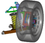
Simulate all aspects of mechanism motion.
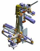 Motion Professional is the complete virtual testing package for designers and engineer. Using animations and XY plots you will
size motors/actuators, determine power consumption, layout linkages, develop cams, understand gear drives, size springs/dampers, determine
how contacting parts behave, generate operating loads suitable for use by Finite Element Analysis, and much much more. Knowing this
information will help you answer two fundamental engineering questions: "Will it work?" and "Will it break?". If you
are a designer or engineer interested in understanding the performance aspects of your design before physical prototyping, you need Motion
Professional.
How to use Dynamic Designer Motion Professional
Mechanism Animation
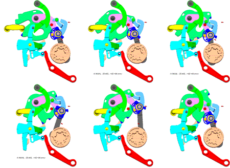 You
will animate mechanisms based on the assembly constraints, any additional
constraints, and actuators you put in the model. A VCR-type interface
provides complete and intuitive animation control. Animations are
ideally suited to visualize the physical motion of your mechanism.
In addition to seeing the motion you can save it to an AVI
(movie) or a VRML (3D animated web format) file.
For more detailed motion analysis, you will visualize animations synchronized with XY plots of engineering data. You will use plots and mechanism motion together to identify possible system failure, part breakage, and safety issues.
Moving Interference Detection
Have you ever built a mechanism containing interfering parts? With Motion Professional you can eliminate interferences before you build the physical hardware. You will check for interferences between parts as the mechanism moves through the real operating range. In addition, you can tell the software to find the first occurrence of an interference or to calculate the minimum distance between parts. An intuitive interference browser lists all steps containing part interferences and selecting an interference highlights it in the model.
Engineering Data
You will use the engineering data available in Motion Professional
to really understand if your mechanism will work. Animations are
perfect for getting a basic understanding of the mechanism and communicating
that understanding to others. XY Plots are critical to gain intimate
knowledge of how the mechanism works. With Motion Professional
you can plot displacement, velocity, acceleration
and reaction load/moment engineering data. Presented in XY
plots, the raw engineering information is complimented with computed
information like power consumption, kinetic energy, potential energy,
and 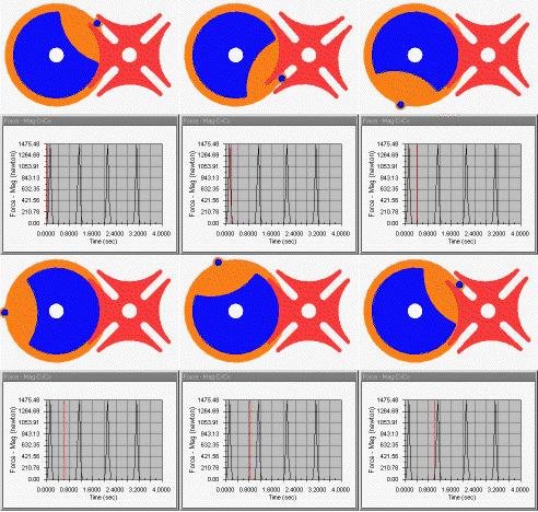 momentum.
The XY plots will help you identify key events by allowing you to
overlay multiple values on a single plot and creating multiple plots.
For additional and customized data analysis, the underlying numerical
data can be exported to Excel.
Contacts
The motion of many mechanisms results from contacting parts. For example, consider a sprocket contacting a chain, a latch contacting a hook, a cam driving linkages, and backlashing gears. Simulating contacting parts is as simple as selecting the two (or more) contacting parts, specifying the associated materials, and running a simulation. The resulting output is accurate 3D motion and XY plots of the underlying information.
Dynamic Designer supports both 3D solid-to-solid and 2D curve-based contacts. The combination provides both power and efficiency. 3D contacts are the most general/powerful while 2D contacts are more efficient. Dynamic and static friction effects can be accounted for in both forms of contacts.
In addition to animation visualization tools, you can plot numerous useful engineering data including contact force and reaction loads. These data will help you quantify important design criteria like bearing loads and part size.
Cams and Gears
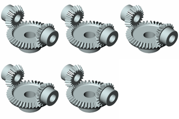 You will be able to understand complex cam and gear mechanisms using
Dynamic Designer Motion Professional. There are two ways
to incorporate cams and gears into your motion simulation: using
contacts or kinematic cam and gear elements. Contact
capabilities, discussed above, provide tremendous flexibility and
will help identify cam liftoff and gear backlash situations. The
kinematic cams and gears are very efficient, but will not show liftoff
and backlash conditions. Kinematic cams are simple to define using
either a point-to-curve or curve-to-curve. Kinematic gears are defined
by simply coupling the motion of one constraint/joint to the motion
of a second constraint/joint (e.g. one joint rotates 3 times for
every single rotation of a second joint).
Dynamic Designer outputs valuable data to help you understand if your cam-driven and gear-driven mechanisms will work including animations, displacements, velocities, accelerations, and forces. You will use this information to size actuator systems, assess cam liftoff situations, limit gear backlash, and reduce part stress/strain.
Constraints/Joints
Mechanisms have parts connected, or constrained, together and move according to the connections. For example, a pendulum can rotate in a single plane relative to the part to which it is connected. Motion Professional offers a comprehensive list of constraints (or joints) to connect parts together. Examples include hinge (revolute), slider (translational), universal, ball (spherical) joints, and many more. Joint friction is available for each joint so that you can accuractely model the physical reality.
Force Driven Motion
Forces are constantly acting on the mechanisms you build. Motors apply a torque to drive a mechanism. Friction effects the actuator size required to drive your mechanism. Nonlinear springs load mechanisms. Dampers stabilize spring loaded parts. Motion Professional helps you build these forces, and many other, into your virtual prototype. Including these forces allows you to accurately model the physics of the mechanism.
Loads for Finite Element Analysis
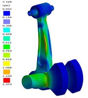 If
you use Finite Element Analysis (FEA) applications to answer the
"Does it break" question by analyzing parts or assemblies
that move, Motion Professional can provide information that can
substantially increase the accuracy of your analyses. As
parts or assemblies move, it becomes very difficult to know what
loads to add to your FEA model, and in what position the worst case
loading conditions occur. Motion Professional calculates accurate
loading conditions, including inertia effects, and can help
you determine where the maximum stresses will occur. Motion Professional
supports direct interfaces to leading Solid Edge based FEA products
such as DesignSpace.
Interfaces
Motion Professional opens to door of communications with complementary packages including popular FEA packages (DesignSpace) and high-end ADAMS virtual prototyping solutions.
Motion Builder
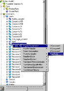 Motion Builder technology helps automate the motion simulation
process making it available to even the most causal user. The Intellimotion
builder is a wizard that helps you quickly build motion models.
It logically takes you through each step, asking key questions and
gathering information as it generates the motion model. The resulting
model is ready to put into motion and see the results.
Motion Browser
Motion Browser technology helps automate the motion simulation process making it available to even the most causal user. There are two ways to interact with Dynamic Designer Products: through a pull down menu and through the Intellimotion browser. The browser is a seamless extension of CAD tree tools. All Dynamic Designer functionality is available through the tree browser including motion model construction, simulation, and result viewing.


 Quote
Quote Evaluation


