Dynamic Designer Motion
CAD Embedded Motion Simulation
Designing One-of-a-Kind Packaging Equipment with Confidence
|
Kimberly-Clark’s engineers had never designed machines quite like those needed for a new tissue-packaging line. And the equipment had to work right the first time. CAD-embedded motion simulation made it happen. |
|
Equipment for these applications is continually pushed to its limits in plants around the world for optimal speed, performance, and uptime. Generally custom-designed and one of a kind, the special-purpose machines impose some of the most demanding and specialized design and production requirements of any industrial equipment. As a result, companies rely increasingly on the power of CAD and simulation tools to develop the equipment and maximize running speeds. Recently, Kimberly-Clark, a major paper-products manufacturer, faced these challenges in the installation of a new high-speed production line for Kleenex facial tissues at a manufacturing facility in Australia. Some of the equipment was designed in-house, with know-how carefully guarded by the company. One aspect of the design involved a high-speed registration device for handling "clips" of folded tissue that get placed in cardboard cartons later in the process. Engineers at the facility had no first-hand experience with the process, but the device was an essential part of the new production line and had to work perfectly the first time so factory operations were not disrupted. |
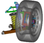
Simulation Made EasyThe equipment was designed by Kimberly-Clark engineers using 3D CAD. So for verifying the functions of the various moving parts (including the clips of tissue), it was a natural progression to model these components and study their motion at various speeds with Dynamic Designer software from Mechanical Dynamics, Inc. The software is embedded in the CAD system, and the integration allowed easy translation back and forth from the CAD models and construction drawings to the dynamic model. Based on component geometries defined in CAD, engineers used Dynamic Designer to add connecting joints along with component forces and motion generators to produce a fully functioning computer model of the mechanical system. What impressed Kimberly-Clark was the speed and relative ease of modeling the process in Dynamic Designer, as well as the ability of the software to model the actual dynamics of the machine. According to the project engineer, the clips were not always mechanically constrained, but the software was able to predict and display their movement as dictated by gravity, friction, and their own inertia. This was said to be very useful in optimizing component geometry and led to a good deal of confidence when it came time to go from drawings to fabricating the equipment. "What-if" Scenarios
Hindsight now shows that the first design would not have worked at all, whereas the final arrangement proved in practice to function very well and much as predicted. No changes were needed to the final machine configuration, other than minor adjustment. Although Kimberly-Clark has used computer simulation for years as a valuable tool in studying continuous chemical processes and product warehousing, this was their first experience with this type of mechanical system simulation, which engineers continue to rely upon in working with the automated production equipment. The dynamic model is now available for future tweaking, alterations to the process, or troubleshooting production problems. Directly comparing actual videos with computer predictions remains an extremely useful tool, allowing engineers to examine the effects of changes in surface friction, for example. |
 Automated
equipment for processing and packaging disposable consumer items
such as razor blades, toothbrushes, and tissues run at high speeds
unheard of only a few years ago. The machines include state-of-the
art electronics, sensor technology, and advanced servo controls
that operate alongside traditional mechanical assemblies and components
made up of tried-and-true cams, linkages, and gears.
Automated
equipment for processing and packaging disposable consumer items
such as razor blades, toothbrushes, and tissues run at high speeds
unheard of only a few years ago. The machines include state-of-the
art electronics, sensor technology, and advanced servo controls
that operate alongside traditional mechanical assemblies and components
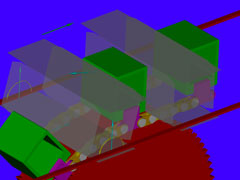
made up of tried-and-true cams, linkages, and gears.  The
properties of the clips were first estimated and then confirmed
by comparing Dynamic Designer predictions with high-speed videos
from similar applications. The final design was developed from dynamic
simulations through a "what-if" process of studying alternative
design ideas.
The
properties of the clips were first estimated and then confirmed
by comparing Dynamic Designer predictions with high-speed videos
from similar applications. The final design was developed from dynamic
simulations through a "what-if" process of studying alternative
design ideas. Quote
Quote Evaluation


