Working Model 2D
2D Dynamic Motion Simulation

Consultants Use Working Model to Isolate Source of Fatigue Cracks
Noble Denton and Associates, Inc. (NDAI) of Houston, Texas is an engineering consulting firm that serves the offshore petroleum exploration and production industry, providing services to companies worldwide. Recently the owner of a mobile offshore drilling rig came to NDAI with a frustrating maintenance problem. The client had noticed on a routine inspection of the unit's steel tubular leg structures the presence of small fatigue cracks. The mobile rig had recently been working off of West Africa, and was due to be moved to a new location. NDAI was asked to isolate the source of the fatigue cracks and propose a solution.
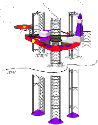
The platform of this drilling unit is a triangular hull 30 feet deep and 200 feet on each side. The platform supports a drill derrick for operations in a marine environment. The platform is supported by jack-ups, three legs that pass through the buoyant hull structure, via legwells, near the three corners of the hull. These legs are about 400 feet in length and can be lowered until they contact the sea floor and begin to raise the platform up until the hull bottom is higher than the crests of the waves.
An unusual challenge
Typically, the legs of a jack-up are steel frame structures composed of chords, vertical steel tubes running the full length of the leg, and framed together with horizontal and diagonal braces, creating a square girder structure. On two of the vertical chords (on diagonally opposite corners) are rows of teeth called racks that run the length of the leg. The racks are engaged by pinions with the same size teeth that are used to drive the leg up or down. Upon departure from a site, the legs are raised and the unit floats with the legs reaching high above the hull, looking like an upside-down table. With the legs so high in the air, some rocking of the legs occurs while the rig is in motion. To keep the legs from rotating too freely, there are guides above and below the pinion mechanism allowing less than one-half-inch clearance.
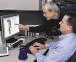
It was an intriguing problem, particularly since it would call for analysing an existing structure to locate the source of the fatigue defect. Because of this unusual challenge, Dr. David Smith, a structural engineer with NDAI, determined that motion analysis was needed. He had read a review of a program called Interactive Physics, an educational program made by Design Simulation Technologies. When he inquired about it, he discovered that Design Simulation Technologiesalso made a desktop analysis tool for industry called Working Model. He decided to try Working Model to analyse the jack-up problem.
Although the legs had a 360-degree range of motion while in the raised position, Dr. Smith felt the problem could be adequately modelled and analysed in two dimensions because “it was clear that the movement of the legs was fairly restricted to a 2-D plane, as the legs would rotate on the diagonally opposed pinions.”
Sketching the mechanism
“We used Working Model to analyse the effect on the legs by simulating the rolling motion of the transportation barge,” said Dr. Smith. Using the Working Model Workspace, Dr. Smith sketched the key elements of the jack-up mechanism. This was done by using the mouse to click on a menu of items that construct the basic elements for any motion simulation, including springs, rods, actuators, dampers, pin joints, rigid joints and polygons. To generate as realistic a simulation as possible, Dr. Smith had to model a leg as a flexible body, not as one rigid structure.
“I modelled the leg as a series of discrete elements and put in torsional springs between the segments to get the bending stiffness just right.” By breaking up the leg into separate sections, Dr. Smith was able to model the flexibility of a jack-up leg realistically as it was acted upon by the simulated wave motions.
To re-create the jack-up mechanism, Dr. Smith modelled the guides on either side of the legs as springs with gaps that only became activated at certain points during the simulation. “When the spring length was under a certain number, it was in contact [with the leg], and when it was over that number, there was a gap so no spring was in effect. Then I used a separate driving actuator to simulate the hull motions and push the whole mechanism around.” He defined the functions of each actuator and damper from the pulldown menus and dialog boxes that permit the user to input specific equations for force and duration, or to select from defaults that speed up the kinematics/dynamic analysis process.
Once the leg and jack-up mechanism were modelled to his satisfaction, Dr. Smith concentrated on identifying the particular forces to apply and in which combinations. The roll of the platform while being towed actually caused a number of different frequencies to interact upon the legs simultaneously. The three that Dr. Smith was most interested in were the sea wave period (which varies with the weather); a leg's own natural swaying period in the upright position (which, for analysis purposes, amounted to an inverted pendulum); and the leg as a cantilever beam (with its own characteristic bending stiffness).
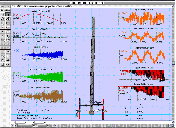
The Noble Denton engineer specified degrees and duration of amplitude, linear air resistance, and other parameters to apply to his simulations, again using the easy-to-follow selections from Working Model's “Measure” and “Windows” pulldown selections. Dr. Smith then chose the different graphic meters that he wanted to display beside his simulation iterations, displaying “Net Horizontal Damper Force,” “Bending Moment,” and other specific results generated from running the simulations. Dr. Smith was particularly interested in the torsional or bending moment of the legs. With each simulation, the engineer altered amplitudes and wave frequencies, monitoring the results with the meters on screen and outputting hard copy of this data for further study.
Confidence in results
Working Model found that the gaps between the pinion guides and the legs themselves could not be ignored. Dr. Smith could tell from his simulations the number of bending cycles that occurred per hour was directly associated with increasing fatigue damage. “Normally the beam stresses are incredibly low when secured,” explained Dr. Smith, “but if you have gaps in the system, they're going to increase because the gaps allow a good whipping action.” Working Model demonstrated that the bending stresses in the legs were amplified most at low amplitude wave motions.For short tows, the way the legs of the jack-up were secured had been considered adequate, but what Dr. Smith discovered with Working Model was the gap between the legs and the pinion guide mechanism was still too great, and as the barge rolled in the natural wave environment, the legs underwent more chaotic behaviour; the legs were bouncing off the guides first on one side and then on the other.
When examined closely with Working Model, it was clear that the bouncing action of the unsecured legs was unpredictable, that is, “the intervals or cycling back-and-forth motions were not regular because of all these varied frequencies.” Ultimately, Dr. Smith and his colleagues concluded that any gap between the legs and the guides was unacceptable, that clamping the legs while in transit was the only way to avoid the fatigue problem.Working Model made it possible for NDAI to be certain that the “guide gaps” were the problem. In fact, there would have been no way for Noble Denton to analyse this problem with complete confidence in the results without a kinematics/dynamics analysis program such as Working Model. As an example, Dr. Smith pointed to the way he modelled the legs as flexible bodies, using torsional springs between rigid leg masses. “If I hadn't subdivided the beam with the rotational springs, and just modelled it as one rigid element, I would never have seen the high frequency bending.”
Working Model performed so satisfactorily on the leg jack-up problem that Dr. Smith and his colleagues have plans to use its powerful analysis capabilities to test future designs. And Noble Denton's client no longer has a fatigue crack problem that causes equipment damage and cuts into the oil profits. Working Model, according to Dr. Smith, demonstrated that it is not only a fine tool for analysing prototypical designs, but in fact makes an excellent kinematics/dynamic diagnostic tool for existing designs.


 Quote
Quote Evaluation


